Understanding Gallons Per Minute (GPM) in Pipe Sizing
Gallons per minute (GPM) signifies the volumetric flow rate of liquid, crucial for pipe sizing. Accurate GPM determination is essential for efficient system design, preventing pressure drops and ensuring adequate water supply. Charts, tables, and formulas aid in GPM calculation, considering factors like pipe diameter and pressure. Proper pipe sizing prevents issues like water hammer and ensures optimal performance.
Factors Affecting Flow Rate
Several key factors influence the flow rate (GPM) in a piping system. Pipe diameter is paramount; larger diameters allow for greater flow due to increased cross-sectional area. Fluid viscosity plays a crucial role; thicker fluids flow more slowly than thinner ones. Pressure is another significant factor; higher pressure generally leads to higher flow rates, but excessive pressure can cause damage. Pipe length also affects flow; friction within the pipe causes pressure loss over distance, reducing flow rate. Finally, the pipe’s internal roughness (material and condition) impacts flow; rougher pipes create more friction, lowering flow.
Pressure and its Influence on GPM
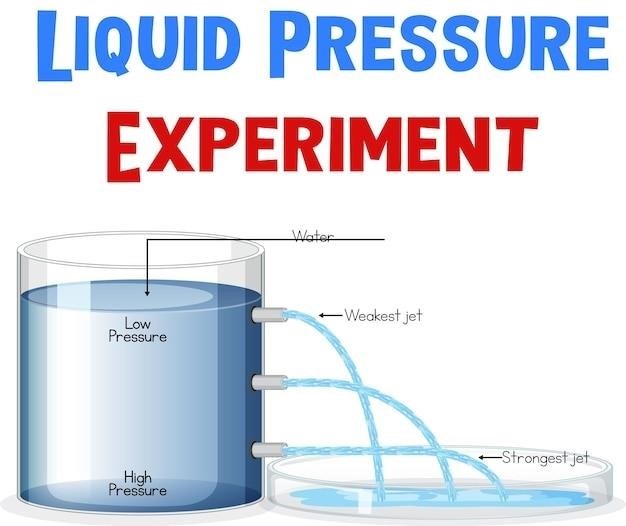
Pressure significantly impacts the gallons per minute (GPM) flow rate within a piping system. Higher pressure generally results in a higher GPM, as the increased force propels the fluid through the pipe more effectively. Conversely, lower pressure leads to reduced GPM. However, this relationship isn’t strictly linear; friction losses within the pipe, influenced by factors like pipe length, diameter, and roughness, counteract the pressure’s effect. Excessive pressure can also be detrimental, potentially causing pipe damage or leaks. Therefore, maintaining appropriate pressure is crucial for optimal GPM and system longevity. Understanding the pressure-GPM relationship is vital for efficient system design and operation.
Pipe Diameter’s Role in GPM
Pipe diameter is a critical factor influencing gallons per minute (GPM) flow rate. A larger diameter pipe offers a greater cross-sectional area, allowing for a larger volume of fluid to pass through per unit time, thus increasing GPM. Conversely, a smaller diameter pipe restricts flow, leading to a lower GPM. This relationship is directly proportional; doubling the diameter significantly increases the flow capacity. However, simply increasing diameter isn’t always the solution, as it can lead to excessive material costs and potentially affect pressure. Optimal pipe diameter selection requires balancing flow requirements with practical considerations like cost, space constraints, and pressure limitations. Careful consideration of these factors is essential for efficient and cost-effective piping system design.

Using Charts and Tables for GPM Calculation
Various charts and tables simplify GPM calculations. These resources provide pre-calculated values for different pipe sizes and pressures, eliminating complex formula use. They offer quick estimations for various applications, saving time and effort in pipe sizing projects.
Interpreting Flow Rate Charts
Flow rate charts typically present GPM values against pipe diameter, providing a visual representation of the relationship between these two parameters. Understanding these charts requires careful attention to the chart’s axes and units. The horizontal axis usually represents pipe diameter (inches or millimeters), while the vertical axis displays the corresponding GPM flow rate. Different curves might represent various pressures or pipe materials (e.g., HDPE, PVC). To find the GPM for a specific pipe size, locate the diameter on the horizontal axis, then trace vertically upwards to intersect the relevant curve. The corresponding value on the vertical axis indicates the flow rate. Remember to always verify the chart’s units and conditions (e.g., water temperature and viscosity) for accurate interpretation. Accurate interpretation ensures correct pipe sizing for your specific application.
Reading Pipe Size Charts for Various Flow Rates
Pipe size charts, often presented as tables or graphs, are invaluable tools for selecting appropriate pipe diameters based on desired flow rates (GPM). These charts usually display pipe sizes (nominal diameter, inner diameter, or outer diameter) in one column and corresponding flow rates in another. Different sections might categorize pipes based on material (e.g., PVC, steel) or pressure class. To use these charts, begin by identifying your required GPM. Then, locate this flow rate within the chart. The corresponding row will indicate the suitable pipe size. Consider factors such as pressure drop, friction loss, and maximum velocity when making your selection. Charts may also include additional information such as pressure drop per unit length for different flow rates within a specified pipe size. Always ensure compatibility between the chart’s specifications and your project’s requirements for optimal performance and longevity.
Deciphering Pressure Drop Charts
Pressure drop charts visualize the relationship between flow rate (GPM), pipe diameter, and pressure loss over a given pipe length. These charts are crucial for designing efficient piping systems, as excessive pressure drops can hinder performance and lead to equipment malfunction. Typically, these charts present pressure drop (often in psi) as a function of flow rate (GPM) for various pipe sizes and materials. To interpret these charts, locate your desired pipe size and material. Then, find the intersection of your target flow rate (GPM) and the corresponding curve for your chosen pipe. The pressure drop value at this intersection represents the pressure loss expected for that specific configuration. These charts often consider factors like pipe roughness and fluid viscosity, influencing pressure loss calculations. Analyzing these charts ensures adequate pressure is maintained across the system for effective operation, avoiding system inefficiencies.

Calculating GPM⁚ Formulas and Methods
Precise GPM calculation employs various methods. The Hazen-Williams equation, for instance, factors in pipe characteristics and flow velocity. Alternatively, multiplying cross-sectional area by flow velocity provides GPM. Online calculators offer simplified computation.
The Hazen-Williams Equation for GPM Calculation
The Hazen-Williams equation is a widely used empirical formula for calculating the flow of water in pipes. It’s particularly useful for determining the friction head loss in a pipe, a crucial factor in determining the GPM. The equation considers several key parameters⁚ the pipe’s diameter, length, the Hazen-Williams roughness coefficient (C), and the flow rate (Q). The roughness coefficient (C) reflects the pipe’s internal surface condition; smoother pipes have higher C values, leading to lower head losses. Different materials exhibit varying C values. The equation itself is relatively complex but readily solvable using calculators or software. Accurate input of all parameters is vital for obtaining a reliable GPM calculation. Remember that the Hazen-Williams equation is an empirical formula, so its accuracy depends on the applicability of the underlying assumptions to the specific pipe system. Variations in temperature and water properties can also slightly affect the results.
Calculating GPM Using Flow Velocity and Cross-Sectional Area
A fundamental approach to determining GPM involves utilizing the flow velocity and the pipe’s cross-sectional area. The volumetric flow rate (Q), measured in gallons per minute (GPM), is directly proportional to both these factors. First, calculate the cross-sectional area (A) of the pipe using the formula for the area of a circle⁚ A = πr², where ‘r’ is the pipe’s radius. Remember to convert units consistently (e.g., inches to feet). Next, measure or determine the flow velocity (v) of the water within the pipe, typically expressed in feet per second (fps). This can be achieved using various flow measurement techniques. Finally, apply the equation⁚ Q = A * v. This equation yields the volumetric flow rate (Q) in cubic feet per second (cfs). Convert cfs to GPM using the appropriate conversion factor (approximately 7.48 gallons per cubic foot and 60 seconds per minute). Ensure all measurements are accurate to minimize calculation errors. This method provides a straightforward way to estimate GPM for simple pipe systems.
Online GPM Calculators and Their Applications
Numerous online GPM calculators simplify the process of determining flow rates, eliminating manual calculations. These tools often require inputting key parameters such as pipe diameter, flow velocity, or pressure drop. The calculators then apply relevant formulas, including the Hazen-Williams equation or variations thereof, to compute the GPM. The ease and speed offered by online calculators are particularly beneficial for quick estimations and preliminary designs. They are widely used by engineers, plumbers, and homeowners alike for various applications. However, it’s crucial to select a reputable calculator and understand its underlying assumptions and limitations. Inputs must be accurate to ensure reliable results. While convenient, online calculators should be used judiciously, particularly for critical applications where precise calculations and thorough verification are paramount. Always double-check results using alternative methods when possible.
Practical Applications and Considerations
Proper pipe sizing is crucial for various applications, from residential plumbing to industrial processes. Understanding pressure drop and water hammer effects is essential for system optimization and longevity, ensuring efficient water flow and preventing damage.
Sizing Pipes for Specific Flow Demands
Accurately sizing pipes to meet specific flow demands is critical for efficient system performance. Insufficient pipe diameter leads to excessive pressure drops, reduced flow rates, and potential system failure. Conversely, oversized pipes are wasteful, increasing material costs and potentially causing unwanted water hammer effects. Several factors influence this process, including the desired GPM, the fluid’s viscosity, and the pipe’s material. Consult flow rate charts and tables, using the Hazen-Williams equation or similar formulas, to determine the appropriate pipe diameter for your specific flow requirements. Consider peak demand and future expansion needs when making your selection. Remember to account for fittings, valves, and other components that contribute to frictional losses within the system. Careful planning and precise calculations are essential for optimal pipe sizing.
Addressing Pressure Drop in Piping Systems
Pressure drop, the reduction in fluid pressure as it flows through a pipe, is a significant consideration in piping system design. Friction between the fluid and the pipe walls, along with fittings and changes in elevation, all contribute to pressure loss. Excessive pressure drop can severely limit flow rate and system efficiency. To mitigate pressure drop, engineers employ several strategies. These include increasing pipe diameter to reduce frictional resistance, utilizing smoother pipe materials, minimizing the number of fittings and bends, and ensuring proper pipe slope in gravity-fed systems. Pressure drop charts and calculations based on factors like pipe length, diameter, and fluid properties assist in predicting and managing pressure losses. Careful attention to pressure drop is crucial for ensuring the consistent and reliable performance of piping systems across diverse applications.
Understanding Water Hammer and its Impact on GPM
Water hammer, also known as hydraulic shock, is a significant phenomenon impacting gallons per minute (GPM) flow in piping systems. It occurs when the flow of water in a pipe is rapidly stopped or significantly changed, creating pressure surges that can damage pipes and fittings. This sudden deceleration of water generates pressure waves that travel back and forth through the system, causing significant pressure fluctuations. The severity of water hammer is influenced by factors like the length of the pipe, the speed of flow, and the material properties of the pipe itself. Mitigation strategies include installing air chambers or surge tanks to absorb pressure waves, employing check valves to prevent backflow, and using slower-closing valves to reduce the suddenness of flow changes. Ignoring water hammer can lead to costly repairs, system failure, and disruption of water supply. Understanding its mechanics and implementing preventive measures are crucial for maintaining optimal GPM and system longevity.